


Project Brief
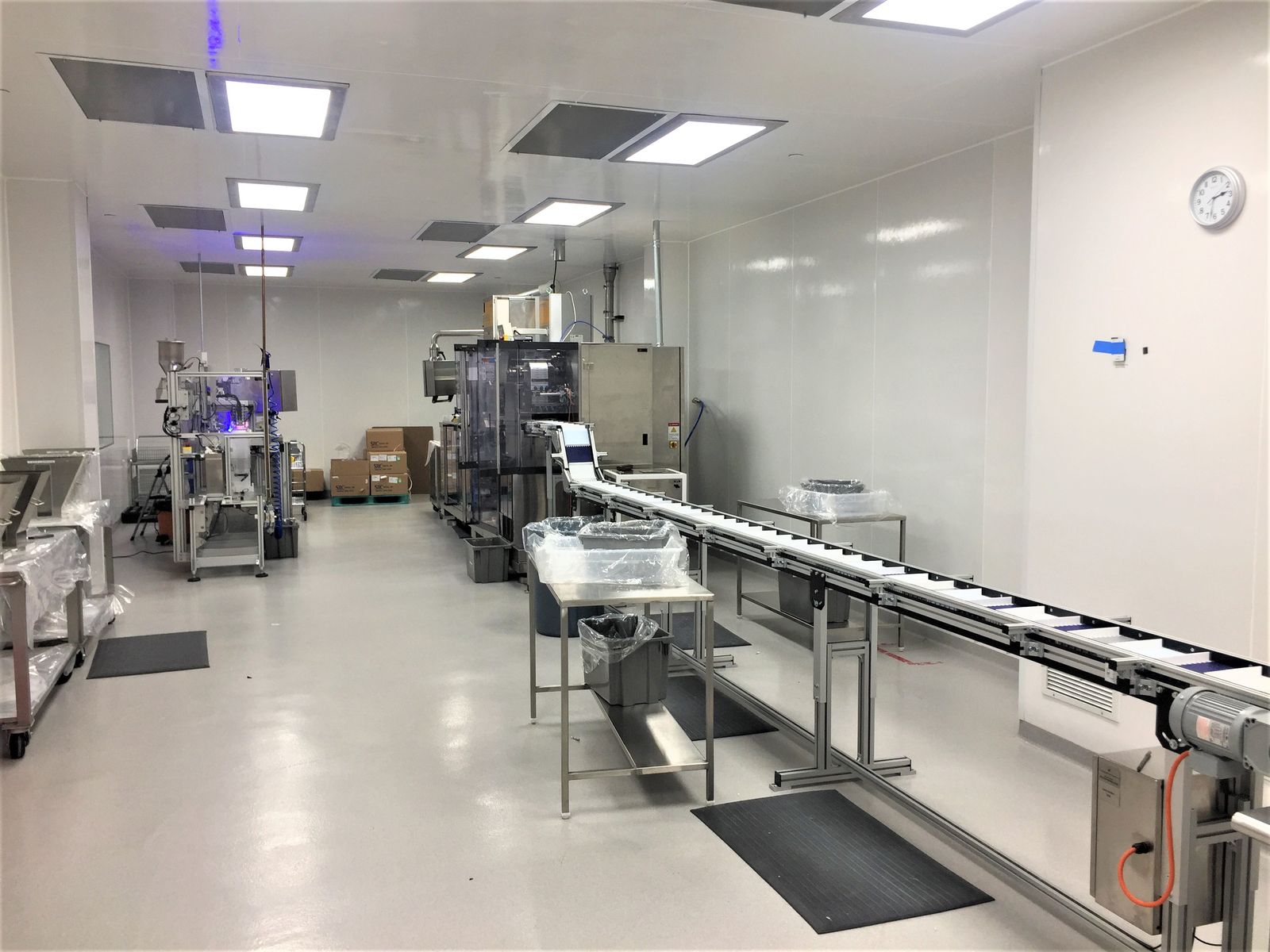
KeRi Engineering provided the mechanical, electrical, plumbing and fire protection design for a new hormonal oral solid dose manufacturing facility, built as a two-story structure of roughly 9,000 SF per floor inside a client's existing, operating warehouse. The plant runs API storage and sampling, dispensing pharmacy, solution preparation, high-shear and fluid-bed granulation, compression, coating, gel cooking and softgel encapsulation, a drying tunnel, sorting, printing and inspection, blister, cartoning, bottle and secondary packaging, a quality laboratory, and a gowning, de-gowning, airlock and air-shower sequence.
A room-by-room user requirement specification set the conditions for 63 rooms: encapsulation at 59 to 68 degrees Fahrenheit and 15 to 30 percent relative humidity, the drying tunnel and the sorting, printing and inspection rooms at 15 to 40 percent, API storage, pharmacy, compression and blister at not more than 45 percent, and the general production suites at 50 plus or minus 5 percent. Classified spaces are ISO 7 at 40 air changes per hour and ISO 8 at 20, with pressure differentials of 0.04 to 0.16 inches of water column cascading through airlocks from the cleanest rooms outward.
Because hormonal compounds are potent and the facility had to accept solvent service later, the air systems are once-through rather than recirculating. Four rooftop units supply 75,200 CFM of 100 percent outside air, MERV 8 and MERV 14 at the unit and 99.99 percent HEPA at the room, with natural gas post-heating and electric pre-heating. Two gas-reactivated desiccant units carry what cooling alone cannot hold: 4,000 CFM removing 125 pounds of moisture per hour for softgel encapsulation, and 6,000 CFM for the drying tunnel. Nine clean-steam humidifiers hold the wetter rooms to within 5 percent.
Process cooling is two 76-ton air-cooled chillers, duty and standby, on a 40 percent glycol loop at 54 and 44 degrees Fahrenheit, keeping production equipment off the building load. A steam-to-hot-water heat exchanger rated 1,263 MBH serves the process hot water loop. The facility draws 3,302 kVA connected and 2,641 kVA demand, fed from a new 3,000 A, 480Y/277 V, 65 kAIC bus with 1,200 A and 800 A distribution panels and 112.5 kVA transformers to 208Y/120 V. The granulation, coating, pharmacy, solution preparation and alcohol storage rooms are explosion-proof, with devices specified to Class I Division 1.
MEP Engineering Scope
What We Engineered
MEP and fire protection design for the new two-story facility:
- ISO 7 and ISO 8 cleanroom design at 40 and 20 air changes per hour, built inside an operating warehouse
- Room-by-room pressure cascade from 0.04 to 0.16 inches of water column, mapped on a space pressurization diagram
- Four rooftop air conditioning units on 100 percent outside air totalling 75,200 CFM, with MERV 8 and MERV 14 filtration, gas post-heat and electric pre-heat
- Two natural-gas desiccant dehumidification units, 4,000 and 6,000 CFM, for the encapsulation and drying-tunnel suites
- Two 76-ton air-cooled process chillers on a 40 percent glycol loop, duty and standby
- New 3,000 A, 480Y/277 V distribution with transformers, panel schedules and connections to every process machine
- Fire protection tied back to the existing fire pump, with hydraulic calculations by room hazard classification
The Challenge
The facility had to be inserted into a warehouse that never stopped operating, and it had to satisfy two rule sets at once. Pharmaceutically, sixty-three rooms each needed their own temperature, humidity and pressure relationship, several of them far drier than a cooling coil can deliver, with potent hormonal compounds contained and cross-contamination between suites prevented. Under the building and electrical codes, the granulation, coating, pharmacy, solution preparation and alcohol storage rooms are explosion-proof spaces, which wants dedicated exhaust, separation and rated devices, while containment wants a sealed, tightly held room. On top of that, the existing shell's structure, roof and services were never sized for rooftop air handlers, chillers, dehumidifiers and a dust collector, and every tie-in to the live sprinkler and utility systems had to be scheduled around production.
Our Solution
KeRi designed the plant so each requirement is met where it applies rather than imposed across the whole facility. Once-through air on 100 percent outside air removes the cross-contamination path between suites; desiccant dehumidification is applied only to the rooms that need it; venturi air valves and electric reheat give every room independent control so one suite's operation does not move another's pressure; and Class I Division 1 devices are used only in the rooms actually classified. Long-lead equipment was pulled forward into a pre-purchase package issued ahead of the bid set, so the air handlers, chillers, dehumidification units, exhaust fans, filter housings and dust collector could be ordered while the construction documents were finished. On the fire protection side, a new 4 inch sprinkler main was run from the existing fire pump discharge header to the new area and the system hydraulically calculated to each room's hazard classification, with shutdowns coordinated under the client's change control process.
The Air System, Room by Room
Independent Control at Every Room
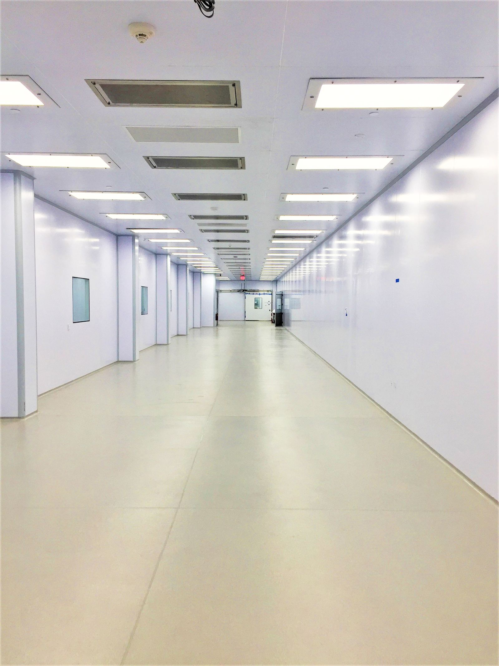
Nothing in this plant is served by a shared zone. Each classified room carries its own devices so its conditions hold whether the rooms around it are running or idle:
- Over 110 venturi air valves, supply and exhaust, with high-speed actuators and fail-safe closed positioning
- Roughly 60 electric reheat coils with SCR control and integral airflow sensors
- Terminal HEPA filters rated 99.99 percent at the room ceiling
- Nine clean-steam humidifiers with auto-adaptive control to within 5 percent relative humidity
- Air valves and devices in the explosion-proof rooms specified to Class I Division 1
Containment and Exhaust
Bag-In Bag-Out HEPA
Nine exhaust filter housings rated 99.99 percent to H13 per EN 1822, with bubble-tight dampers and magnehelic gauges, so potent-dust filters are changed without opening the airstream.
High-Plume Discharge
Five roof exhaust fans on variable frequency drives, from 4,000 to 23,000 CFM, discharging above the roof plane away from the outside-air intakes.
6,350 CFM Dust Collection
A sixteen-cartridge collector picking up granulation, compression, blending, packaging and sampling, with a HEPA after-filter and an explosion isolation flap in the duct outside the building.
125 lb/hr Moisture Removal
Desiccant wheel capacity at the encapsulation unit alone, holding a room that cooling coils cannot dry far enough on their own.
Airlocks at Every Transition
Personnel and material airlocks, an air shower at gowning, and an electric air curtain at the exterior vestibule keep the cascade intact at each boundary.
2,641 kVA Demand
Calculated room by room and machine by machine, which set the 3,000 A service bus the facility is fed from.
Process Utilities to Each Machine
The manufacturing equipment was scheduled with the client before design, so each granulator, blender, coater, press, cooking vessel and packaging line could be brought its own utilities at its own point of use:
AWater and Process Fluids
- Purified water and DI water distribution, sized for 1,300 gallons per day at a 650 gallon per hour peak
- Process cold water and a process hot water loop off a steam-to-hot-water heat exchanger
- City water, 120 degree domestic hot water, and a separate 160 degree closed loop
- Chilled water from the dedicated process chillers to equipment jackets and condensers
BGases and Compressed Air
- Compressed air ports in 28 rooms, from packaging lines to the dispensing pharmacy
- Nitrogen to encapsulation, sampling, granulation, medicine preparation, alcohol storage, pharmacy and solution preparation
- Plant steam at the technical area, including 400 and 1,100 pound per hour points of use
CDrainage and Waste
- Process waste and process floor and equipment drains, kept separate from domestic drainage
- Acid waste and acid waste vent piping tied to the existing central neutralization system
- Sanitary, vent and storm systems for the new two-story structure