

Project Brief
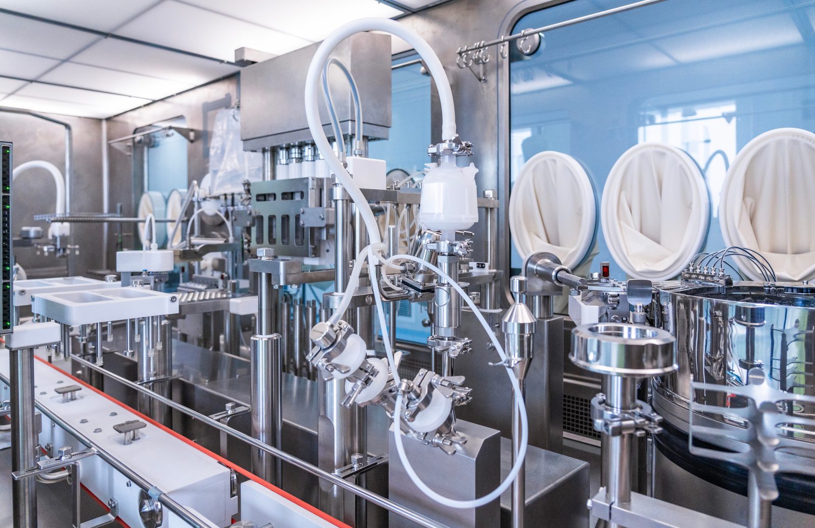
KeRi engineered a sterile injectable fill-finish operation inside an existing 40,000 SF two-story building shell. The program put two high-speed filling lines into that shell along with everything they depend on: sampling and dispensing, solution preparation, washing and depyrogenation, filling and bunging, lyophilization, terminal sterilization, visual inspection, labeling and packaging, clean article storage, QC and media laboratories, gowning and change rooms, warehouse, and the utility technical area that feeds all of it. Working inside a shell set the constraints: every system had to fit the structure, the floor-to-floor heights, and the roof capacity that were already there, which is why the mechanical plant sits on a new equipment platform and the classified rooms were planned around the airflow they needed rather than around the building.
The facility was designed to satisfy the FDA and the EU at the same time. EU GMP Annex 1 governs sterile manufacture in Europe, and its revision, published in August 2022 and effective a year later, was already circulating in draft while this project was being designed. Annex 1 asks a manufacturer for a documented, site-wide contamination control strategy rather than a checklist: every source of microbial, particulate and chemical contamination has to be identified and shown to be controlled, and the guidance pushes hard toward barrier technology, isolators and RABS, around the Grade A critical zone where product is exposed. That shapes engineering directly. The critical filling operations here are enclosed in isolators, the surrounding rooms are classified and held in a pressure cascade so air always moves from cleaner to less clean, air is HEPA filtered at the terminal, and room conditions are monitored continuously so the contamination control strategy has data behind it.
The mechanical design is the bulk of the work: roughly 310 tons of cooling delivered through 11 air handling units, sized room by room from the classification, air-change rate, and pressure relationship each space required. Units serving classified areas carry MERV 8 and MERV 13 stages ahead of 99.97% HEPA final filtration, stainless coil casings and drain pans, and VFDs on supply and return fans. Electric reheat coils at the rooms trim temperature and relative humidity individually. In a hot, humid Southeast climate the latent load is the hard part, so four active desiccant dehumidification units with gas-fired reactivation dry the outside air ahead of the units serving the filling and solution preparation suites, taking the air well below what a cooling coil alone can reach. A 100 BHP natural-gas steam boiler, rated 3,450 lb/hr at 90 psi operating pressure, feeds the plant steam side and the pure steam generator, with condensate return, blowdown separation, and chemical feed on the boiler skid.
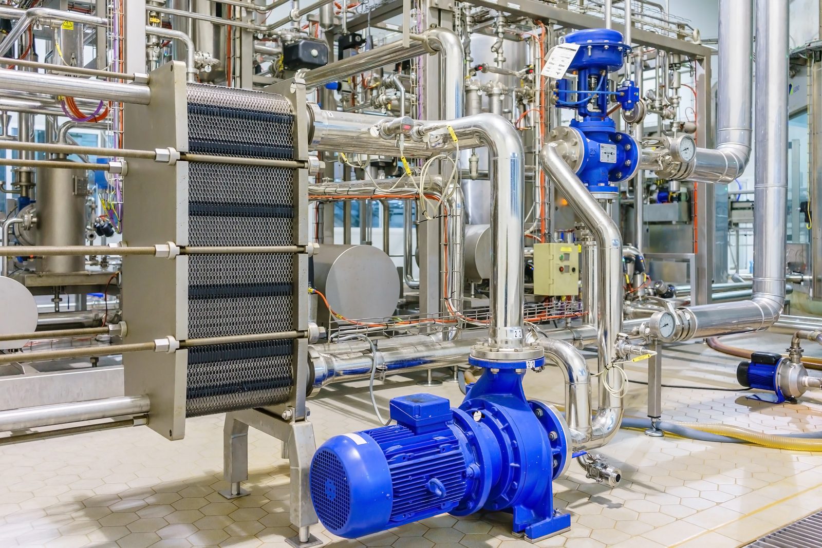
Process utilities were designed alongside the building systems: purified water generation through reverse osmosis and continuous electrodeionization with a 5,000 litre storage and distribution loop, a WFI system with a 3,000 litre storage tank feeding the isolators, vial washing, and the lyophilizer, a pure steam generator for sterilization, a nitrogen system in SS316L piping for product blanketing, compressed air with drying and filtration, process chilled water, process hot water, and the process waste and vent systems that serve them, all laid out with the sanitary detailing and slopes that a validated system needs.
On the electrical side the building took a new 3,000 A, 277/480 V, three-phase, four-wire service against roughly 2,495 kW of connected load, distributed from a main switchboard on the equipment platform. Standby power is 1.5 MW, provided as three 500 kW / 625 kVA natural-gas generators operating in parallel through a synchronizing panel and four automatic transfer switches. Paralleling means the three sets are brought into step with each other on voltage, frequency and phase angle before their breakers close, then share the load evenly, which keeps each machine working in its efficient range instead of one oversized set loafing at low load. It also buys redundancy: the plant can lose or take down one generator and still carry the critical load on the other two, and the sets can be serviced one at a time without dropping standby capability. UPS units back the process equipment and instrumentation that cannot tolerate even the seconds a transfer takes.
MEP Engineering Scope
What We Engineered
MEP/FP and process systems for the two-line sterile injectable facility:
- Classified cleanroom HVAC: 11 air handling units, about 310 tons of cooling, with MERV 8 and MERV 13 pre-filtration and 99.97% HEPA final filtration on the classified units
- Four active desiccant dehumidification units with gas-fired reactivation, drying outside air for the filling and solution preparation suites
- Room-by-room pressure cascade and pressurization diagram, with electric reheat coils trimming temperature and relative humidity space by space
- 100 BHP natural-gas steam boiler, 3,450 lb/hr at 90 psi, with condensate return, blowdown separator, and chemical feed
- Pure steam generation and distribution for sterilization, plus industrial steam for plant services
- WFI generation, 3,000 litre storage and distribution to the isolators, vial washing, and lyophilizer
- Purified water by reverse osmosis and continuous electrodeionization with 5,000 litre storage and a sanitary distribution loop
- Nitrogen generation and SS316L distribution, and compressed air with drying and point-of-use filtration
- Process chilled water and process hot water systems serving the filling lines, autoclaves, and washers
- New 3,000 A, 277/480 V, three-phase four-wire service and main switchboard for roughly 2,495 kW of connected load
- 1.5 MW of standby power: three 500 kW natural-gas generators paralleled through a synchronizing panel, four automatic transfer switches, and UPS backup for critical process equipment
- Fire alarm, sprinkler coordination, process waste and vent, and BMS controls with continuous monitoring of classified room conditions
The Challenge
Two high-speed injectable lines and every utility they depend on had to fit inside an existing building shell, hold classified conditions in a hot and humid climate, satisfy both FDA expectations and EU GMP Annex 1, and keep running through a power loss.
Our Solution
KeRi engineered the building and process systems as one design: classified HVAC with HEPA final filtration and a room-by-room pressure cascade, four active desiccant units to take the latent load the coils could not, a steam plant feeding pure steam for sterilization, WFI, purified water, nitrogen and compressed air designed to sanitary standards, and a 3,000 A service backed by 1.5 MW of paralleled, synchronized standby generation with UPS on the equipment that cannot ride through a transfer.
Previous Project VitaQuest Probiotics Suite Next Project Aseptic Fill-Finish Facility